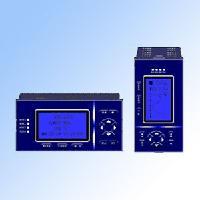
Display instrument anti-jamming measures
 The formation of interference problems is due to the existence of interference sources and influences instrumentation through certain coupling channels. In order to reduce these effects, interference suppression should be considered when designing the instrument and its ability to resist interference should be maximized. In practical applications, it is necessary to find out and combine twisting, shielding, grounding, balancing, filtering, and isolation methods and cut off the coupling channel to suppress interference. At the same time, the display instrument is required to have high temperature resistance, low temperature, high pressure, corrosion, high viscosity, and good dynamic characteristics to reduce the measurement error of the measured parameter.
 Suppression of serial-mode interference: Serial-mode interference may be generated at the source and may be induced or received from the lead. Because the serial mode interference is in the same position as the signal under test, once the serial mode interference occurs, its harmful effects are often not easily eliminated, so it should be prevented first.
(1) Twisting of signal lines: For electromagnetic induction, it is necessary to keep the wires away from the power equipment and the power network. It is necessary to adjust the wiring direction and reduce the wire loop area. Only the alignment direction and two signal lines are adjusted. With a short pitch twist, the interference voltage can be reduced to 1/10 to 1/100; for static induction, when the two signal wires are twisted and twisted and the two signal lines are twisted When the interference sources are approximately the same distance (usually the wire is twisted to a pitch 20 times the diameter), the area surrounded by the signal circuit can be greatly reduced, so that the electric field enters the string through inductive coupling on the two signal lines. The mode interference potential difference is greatly reduced.
(2) Shielding: In order to further prevent electric field interference, the signal line may be wrapped with a metal mesh (or metal skin), and a shielded cable may be directly used as a layer of insulator or signal line on the bread, and the shielding layer may be grounded. Because the non-magnetic shielding layer has no effect on the magnetic field of 50 Hz, if necessary, the signal line can be threaded into the iron pipe to make the signal line magnetically shielded. After electrostatic shielding, the induced potential can be reduced to 1/100~1/1000.
(3) Filtering: For the DC signal with very slow change speed, add a filter circuit at the input end of the instrument to minimize the interference mixed with the effective signal. It is common to add two to three RC filter circuits before the input stage, and to use a double T filter with a lower internal resistance.
(4) Cancellation: Digital instruments, such as double integral type and pulse width type, perform A/D conversion on the mean value of the input signal instead of the instantaneous value, and can average out some serial mode interference. (5) Try to separate the signal line from the power line. Reasonable wiring, under the conditions allowed to wire the current flow to the opposite direction to reduce the mutual interference of the magnetic field; the signal line and the power line are not allowed to be laid together in parallel, should not enter the instrument through the same thread hole Inside. The low-level signal line should be connected to the adjacent position of the signal terminal with the shortest twisted wire as short as possible to reduce the area of ​​inductive interference, and it is absolutely prohibited to use the same cable for the power line and signal line. Do not use the same connector for high and low levels. When it is a last resort, separate the high and low lines next to the connector, with the ground terminal and the backup terminal in between.
Solenoid Coil Hole Diameter 8mm Below
The category of Solenoid Coil which hole diameter is below 8mm. Possible applications are solenoid valves like dust collector pulse valve, refrigeration valve, Pneumatic Valve, hydraulic valve, LPG CNG valve, automobile valve, injector rail, home appliance Solenoid Valve, and so on.
8mm Solenoid Coil, 8mm Hole Solenoid Coil, 8mm Hole Diameter Solenoid Coil
NINGBO BRANDO HARDWARE CO.,LTD , https://www.brandopneumatic.com