Design and Implementation of a Ultrasonic Heat Meter Beam Pipe Fittings
1.1 Ultrasonic Heat Meter Measurement Principle
The ultrasonic heat meter consists of three parts: ultrasonic flow sensor, paired temperature sensor, and calculator. As shown in Figure 1.
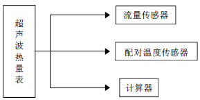
Fig. 1 Block diagram of ultrasonic heat meter
Ultrasonic heat meter is based on the ultrasonic flow meter plus temperature measurement, and the amount of heat supplied to the user is calculated from the flow rate of the fluid and the temperature difference between the supply and return water. The flow measurement part is to apply a pair of ultrasonic transducers to alternately (or simultaneously) send and receive ultrasonic waves, and indirectly measure the flow velocity of the fluid by observing the time difference between the forward and backward flow propagation of the ultrasonic waves in the medium, and then calculating the flow rate through the flow velocity. Indirect measurement method.
1.2 System Structure
This paper designs a supersonic heat meter beam pipe fitting installed in the pipeline of ultrasonic heat meter. The beam pipe fitting is a cylindrical pipe and is fixed on the central axis of the ultrasonic heat meter pipe by positioning and locking screws. The pipe diameter of the pipe is smaller than that of the ultrasonic heat meter, as shown in Figure 2.
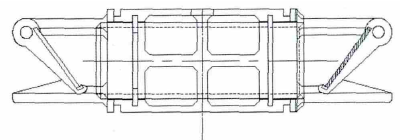
Figure 2 Overall structure
1.3 Key technologies
The premise of the ultrasonic sensor measurement principle is that the liquid flow field in the pipe should be evenly distributed, and the flow rate at each point on the pipe section is the same, and this is only an ideal situation. In practical applications, it is found that the flow field cannot be evenly distributed. The velocity distribution of the flow field is not only related to the flow velocity, the thickness of the pipe, the shape of the pipe, the roughness of the pipe surface, but also the density of the liquid in the pipe, the kinematic viscosity of the liquid, etc. The conditions are related to the measurement accuracy.
The surface roughness Ra of the pipe inner wall of the beam pipe is less than 1.6 μm, ie the arithmetic mean deviation of the profile is less than 1.6 μm.
The tube of the beam pipe is fixed with two mirrors that are 45° from the inner wall of the pipe. The mirrors of the two mirrors are relatively and non-parallel.
Compared with the prior art, the beneficial effects of the present invention are:
The use of beam pipe fittings to adjust the flow field artificially accelerates the heat-carrying liquid flowing through the ultrasonic heat meter, converts the small flow rate into a large flow rate for measurement, improves the uniform distribution of the flow field, and ensures the metering accuracy of the heat meter.
By improving the smoothness of the pipe inner wall of the beam pipe fitting and reducing the difficulty in machining the pipe inner surface of the ultrasonic heat meter, the measurement accuracy of the ultrasonic heat meter is improved while reducing the cost and the difficulty.
By means of a mirror fixed at an angle of 45° on the axis of the pipe of the beam pipe, the signal transmitted by the ultrasonic sensor is reflected, and the effective signal is not easily attenuated, and the service life of the product is improved.
2 Compared with reflection
As shown in FIG. 3 , when the beam tube is not installed, the ultrasonic sensor measures the wall reflection of the base table. The signal emitted by the ultrasonic sensor is usually a reflection mirror on the inner wall of the tube section and has only one reflection point. After catadioptric refraction, the signal is accepted by another ultrasonic sensor to complete the propagation of a signal. However, according to the principle of fluidics, the flow velocity of a fluid in a pipeline varies with its cross-sectional distribution, and its flow velocity is also different. The flow velocity on the central axis is the fastest, the flow velocity is closer to the tube wall, and the flow velocity at the tube wall is zero. The wall of the tube is easily fouled and crystallized, so that the effective signal gradually decays due to the accumulation of time, and thus the service life of the product that depends on the signal wall of the tube wall itself is short.
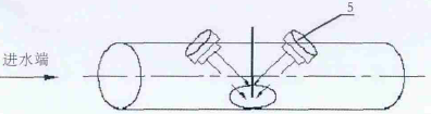
Fig. 3 Schematic diagram of unmounted beam pipe fittings in pipes of ultrasonic heat meters
3 Installation steps
With reference to FIG. 4 and a specific installation manner, the ultrasound heat meter beam pipe fitting is further described in detail.
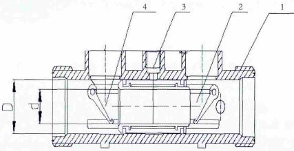
1 ultrasonic heat meter; 2 beam tube; 3 positioning locking screws; 4 mirrors;
Figure 4 Installation of beam pipe fittings
Ultrasonic Heat Meter The beam pipe 2 is a cylindrical pipe, and the pipe 2 of the beam pipe 2 is fixed with two mirrors 4 which are 45° from the inner wall of the pipe. The mirrors of the two mirrors 4 are opposite to each other and are not parallel to each other. The area of ​​the reflector 4 is increased in the beam tube 2, and the measurement accuracy of the ultrasonic heat meter 1 is improved. The beam tube 2 is fixed on the central axis of the ultrasonic heat meter 1 tube by the positioning locking screw 3 so that the mirror 4 is also on the inner axis of the tube. The diameter of the beam tube 2 is D, the tube diameter of the ultrasonic heat meter is d, the diameter of the tube through which the hot fluid passes is artificially accelerated by the heat carrier liquid flowing through the ultrasonic heat meter 1, and the small flow rate is converted into a large flow rate. Perform measurements to improve the uniform distribution of the flow field. The surface roughness Ra of the pipe wall surface of the beam pipe fitting 2 is less than 1.6 μm, ie, the arithmetic mean deviation of the profile is less than 1.6 μm. By improving the smoothness of the inner wall of the beam pipe fitting 2, the measurement accuracy of the ultrasonic heat meter 1 can be effectively improved.
When installing, the reflector 4 is firstly installed on the beam pipe fitting 2 at an angle of 45°, and then the beam pipe fitting 2 is fixed on the axis in the pipe of the ultrasonic heat meter 1 by the positioning locking screw, and the beam pipe fitting 2 is completed. Installation in ultrasonic heat meter 1
What needs to be emphasized here is that each of the modules is a collection of circuit logic instead of a virtual function module. Its specific implementation is a common technical means in the field, and those skilled in the art can read it completely and can reproduce it completely according to the conventional technical means mastered by them.
240 M3/h Concrete Batching Plants
During the maintenance of the mixing station, the main power supply must be cut off, the door of the distribution cabinet must be locked, and the key should be kept by the electrician.Power cutting and transmission must be operated by electrician.When starting the belt conveyor, mixing host, and other motors, it is necessary to observe whether there are people or other sundry things on the motor, in order to prevent injury or damage to the equipment when starting. When cleaning, it is strictly prohibited to flush the electric motor, electrical switch, solenoid valve and other electrical appliances with water to prevent electric shock and damage to electrical equipment.When the mixer is working, it is forbidden to stand in the discharging area.Non-operators are forbidden to enter the control room, smoking and doing things unrelated to the operation are prohibited.There is no operator in the operating room. Power must be cut off and doors and Windows must be locked before leaving.
Hzs Ready Mix Batching Plant,Hzs Mini Concrete Batching Plant,Hzs Batching Plant,Hzs Belt Conveyor Batching Plant
Shandong Zeyu Heavy Industry Science and Technology Co.,Ltd. , https://www.sdjzcseriesdrumconcretemixer.com